ICCA MMC Detroit


    ICCA
  Participants
Username:

Password:


  ICCA REFERENCES

    MMC Detroit References
 IMAGES

   ICCA
 CONTACT INFORMATION

  International Chrysler Collector Authority Section # 9 Production Inspection marks


Paint markings

This section of the ICCA "Finer Points of a Mopar" manual in intended to provide some insight into the paint markings found on Chrysler vehicles. This manual is a work in progress and will be continuously updated as new information is discovered.

It has been a challenge compiling the most accurate and objective assembly information because there were two assembly plants for A bodies, up to five assembly plants for 1966-72 B bodies and two assembly plants for E bodies. Each plant had variations to numerous assembly processes and suppliers of components through out any given production period. However, the ICCA thought about inspection/judging a Mopar is to "never say it's not possible". There are still production processes today that are not consistently followed from day to day or vehicle to vehicle.

There is about 25-30 different paint markings on a vehicle. Just under half of the paint marks that appear were applied by inspectors during the final assembly phase of the vehicle. The majority of the paint marks and grease pencil were already on parts that arrived to the point of assembly from outside suppliers.

Many of the paint marks that are found on vehicles were actually part identification marks. These markings were applied outside of the final assembly point by the supplier of the part. In a high production assembly environment it is more efficient and it reduces the chances of error for the operators to look specific parts for installation to look for identifying colors then to read a part number. It is important to understand that production parts were not delivered to the point of assembly in boxes with part numbers. All parts were delivered in large dunnage containers.

Reference vehicle: 1970 Cuda and Challenger R/T.

The following information has been researched from the inspection of original " survivor type" 1970 Cuda and 1970 Challenger R/T vehicles, interviews with former Chrysler Corporation employees that worked in the quality control department at the final assembly plant and reviewing original Chrysler engineering documentation. However, some of the same inspection and part identification paint marks can be found on other A, B & E models. Please keep in mind this information is for reference purposes only. Variations to the following have been observed.

Some procedures vary between assembly plants. Other marks may have been used early in the model year then relaxed as the assembly line workers understood how to perform their job. Very few vehicles received all the paint ID and/or inspection marks. The types and colors of the ID and inspection marks may very by the assembly plants processes and/or period of production.

The most common places to find paint daubs on the front suspension are the lower ball joints, lower control arms, idler or outer tie rods, idler arms, center link, pitman are, steering box, spindles and torsion bars.

Final assembly Inspection Marks

The paint colors used were primarily very close to the actual vehicle colors offered by Chrysler. However, the paint was a solid color and did not contain metallic flakes.

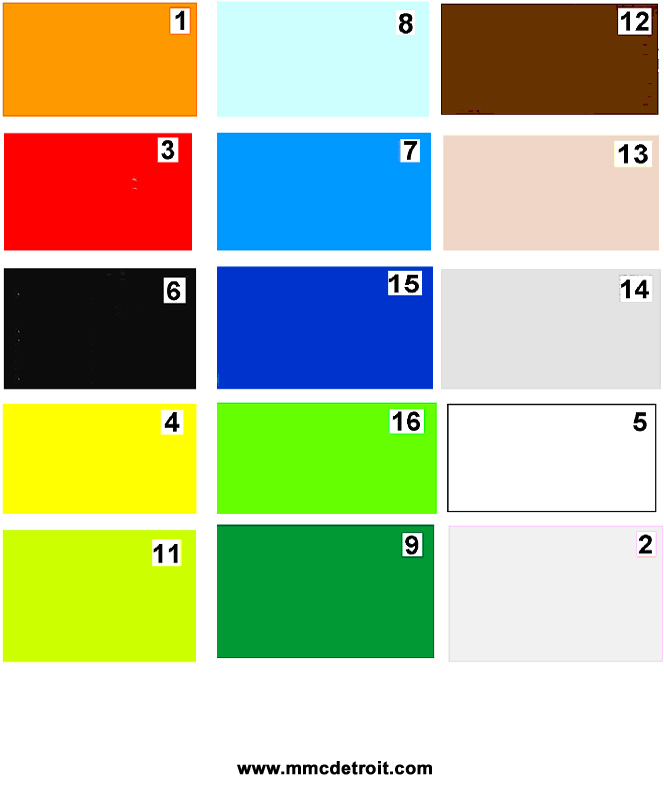
Part Identification color codes

The paint color codes used by suppliers were not the same paint colors that Chrysler offered as vehicle colors. The colors used were typical solid colors (i.e., red, blue, yellow, black, orange, pink, green etc...).
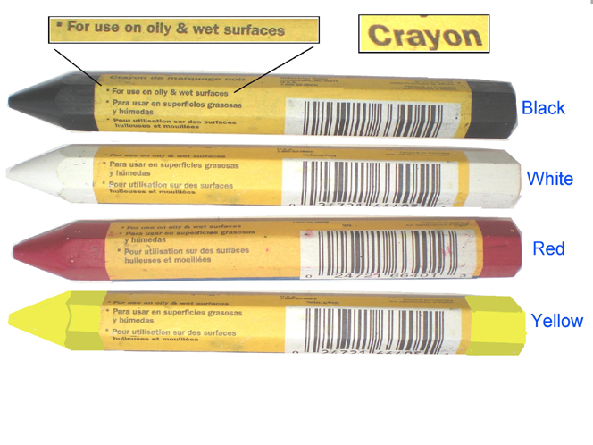
Paint

Inspection/ Identification Paints and Markers

We have the following available for purchase.

  • Large Marking Crayons - Just like the factory used.

Red, Yellow, Black and White. .................$ 3.00 ea. + shipping.

  • Acrylic Paint - Please specify identification numbers (Reference the color chart on the previous page) of desired colors 2 fl. oz. ................$ 4.00 ea. Until further notice paint can no longer be shipped.

Paint
 

Component

Inspection / identification mark

Front suspension components

1

Every steering connection point where tri-castle nuts are used

Orange paint # 1. The cotter pins are typically both bent in the same direction. 1971 Cuda's and Challengers typically were found with lime green # 11 marks.

2

Center Link

Two blue paint swipes #15 - 3/4" wide x 3.00" lg. near the center of the link

3


4

Lower ball joint


a

RH

Orange paint # 1swipe between rear mounting fastener and outer tie rod.

b

LH

None

5

Upper control arm


6

RH

Green paint swipe on leading edge near ball joint

7

LH

Yellow paint # 4 swipe on leading edge near ball joint

8

Front shock absorber

Paint on top of stud or bottom of shock eye

a

RH

Blue # 15

b

LH

Orange # 1

9

Inner fender (Outside)

White paint # 5 swipe 1/2" wide x 4" lg. on each side of upper control arm on the frame

10

Tie rod sleeve


a

RH

None observed

b

LH

Yellow paint # 4 daub near inner tie rod end - 3/4" dia.

Steering related

1

Power steering gear box

White paint # 5 swipe on inside of case. 1/2" wide x 2" lg.

2

Idler arm

None

3

Pitman arm (gear arm assembly)

One blue paint # 15 swipe - 1/2" wide x 2" lg

4

Steering shaft coupler to gear box

White paint # 5 swipe 1 1/2" wide on coupler

5

Horn adapter

Yellow paint # 4 daub

Brake related

1

Front brake caliper mount


a

RH

Orange paint # 1 swipe between bolts - approx 1 1/2" lg

b

LH

Orange paint # 1 swipe between bolts - approx 1 1/2" lg

2

Disc brake caliper


a

RH

White paint # 5 daub near bleeder screw

b

LH

White paint # 5 daub near bleeder screw

2

Disc brake dust shield


a

RH

White paint # 5 daub - 1" dia. just below the lower ball joint front mounting fastener.

b

LH

White paint # 5 daub - 1" dia. just below the lower ball joint front mounting fastener.

3

Brake drum

Red/ orange paint for road and ralley wheels. Applied with wide brush

4

Fire wall near master cylinder


a

Above master cylinder reinforcement plate

Orange paint # 1 daub 3/4" dia.

b

Left master cylinder reinforcement plate

Yellow paint # 4swipe 3/4" wide x 1" lg

c

Power brake booster

Orange paint # 1 daub at top front 3/4" daub.

K member related

1

K member


a

RH side

Orange paint # 1daub approx 1" dia under lower control arm mounting point

b

LH side

Red paint # 3 daub approx 1" dia under lower control arm mounting point

c

RH front

White paint # 5 "X" below and inside of strut rod nut

2

Torsion bars


a

RH 1857778

One aluminum paint # 14 swipes . This mark is 1" wide and approx. 12" from the front.

b

LH 1857779

Two aluminum paint # 14 swipes. Same position as 2a

c

RH 1857780

One brown paint # 12 swipes. Same position as 2a

d

LH 1857781

Two brown paint # 12 swipes. Same position as 2a

e

Dust boot

Red paint # 3 swipe on bottom edge of each dust boot and onto frame.

4

Lower control arm


a

RH


a1

Torsion bar adjuster

Blue # 7 or orange # 1 of Green # 9 paint on tip of adjuster

a2

Rivet that holds the ball joint end

Dk green # 9, yellow # 4 or white paint # 5 on rear of arm

b

LH


b1

Torsion bar adjuster

Yellow # 4 or Blue # 7 or Green # 9 paint on tip of adjuster

K member related cont.

b2

Rivet that holds the ball joint end

Dk. Green # 9, yellow # 4 or white paint # 5 on rear of arm

Rear suspension

1

Rear shock absorbers

Paint swipe on bottom of shock eye typically 1/2" wide x 3/4" lg.

a

RH (E74, E86 & E87)

White # 1and brown #12

b

LH (E74, E86 & E87)

White # 1 and brown. #12

c

RH (E55 & E 65 )

Green # 9 and yellow #4

d

LH (E55 & E65 )

Green # 9 and yellow # 4

2

Rear sway bar

Dk Green # 9 paint daub on outside of mount between mounting bolts

3

Rear spring front hanger

White paint # 5 daub on outside surface near spring eye bolt

4

Rear spring

Two paint swipes on front of spring typically 3/4" wide x 2" lg.

a

RH ( E74)

Blue # 8 and white # 5

b

LH (E 74)

Blue # 8 and white.# 5


Manual transmission

1

Right side of transmission


a

Pipe plug

White paint # 5 "X" above pipe plug - 2 1/2" tall

b

Pipe plug

Lt. blue paint swipe next to pipe plug

c

Transmission code

Large blue paint # 8 stencil (3 digits) above vin ID and part number machined pad

d

Casting number

Med green paint # 16 swipe over casting number


2

Left side of transmission (cover side)


a

Speedometer

White paint # 5 daub above speedometer gear hsg.

b

Side cover upper

White paint # 5 daub at top and center of side cover

c

Side cover lower

Yellow paint daub on bottom bear 2nd bolt from the front

3

Bottom of transmission


a

Pipe plug

Lt. blue paint # 8 swipe next to pipe plug

b

Tail shaft to case mounting

Lt. blue paint # 8 swipe on tail shaft to case mounting area near right side bolt.

4

Top of transmission


a


Lt blue paint # 8 in a Y shape near center left edge

b


Yellow paint daub 1 1/2 " dia. in center

c

Tail shaft to case mounting

White paint # 5 swipe on the tail shaft to case mounting area near top left side bolt.


8 3/4" axle assembly

1

U joint flange

Lt blue # 8 and green paint # 9 daub’s

2

Pinion nut

Lt. blue # 8 or white paint # 5 swipe on pinion nut and flange

3

Differential (3rd member)


a

Final Assembly ID date

Yellow 3 or 4 digit stamp on bottom side of rib on left side

b

Assembly date

White 3 or 4 digit stamp on bottom of left side tube typically inside of inner U bolt (Month model year and week. i.e., 9 F 4 )

c

Axle code

Yellow 3 digit stamp (part number found on build sheet) on front of the tube typically inside of the inner U bolt.

d

Axle ratio tag placement

This tag is placed under the nut at the 2 O'clock position ( left side)

e

Fill plug

Red paint # 3 wipe on back side of plug

f

Fill plug

Orange paint # 1 swipe on front side of fill plug

g

Axle ratio

Paint swipes located on bottom barrel of 3rd member and are about 3/4" wide x 1" lg. - See the following

g1

3.23 axle ratio 1.38" pinion

One blue paint # 15 swipe

g2

3.23 axle ratio 1.87" pinion

Three black paint # 6 swipes

g3

3.55 axle ratio 1.87" pinion

One white paint # 5 swipe

g4

3.91 axle ratio 1.38" pinion

One black paint # 6 swipe

g5

3.91 axle ratio 1.87" pinion

Two orange paint # 1 swipes

h

Sure grip id

One orange paint # 1 swipe located on bottom barrel of 3rd member near the mounting flange

4

Carrier / housing


a

Right tube top

Lt blue paint # 8 swipe on right side tube top near U bolt

b

Left tube top

Large yellow paint # 4 swipe on left tube side near U bolt

c

Rear dome

Large white paint # 5 " E" in a circle on back of housing behind 3rd member

d

Rear dome

Large yellow paint # 4 swipe on back and top between 9 and 11 O'clock position

e

Right tube rear

White paint # 5 in S or G shape on rear of left tube below brass junction block

5

Brake backing plate

Green # 9 or white paint # 5 swipe below the adjuster plugs on each side.

9 1/4 " Dana 60 axle assembly

1

Part ID tag

Strip of white tape with build code in red on left tube just inside of the inner U bolt

2

Axle code

Yellow 3 digit stamp (part number found on build sheet) on rear of the right side tube typically inside of the inner U bolt.

3

Axle tags locations


a

Lubrication tag placement

Under bolt on right side of cover at 5 O'clock position

b

Ratio tag placement

Under bolt on left side of cover at 7 O'clock position. There is typically a yellow paint daub # 4 on the head of the bolt.

4

Bottom of differential

White paint # 5 "X" just behind the pinion flange

5

Left side of differential

Large white paint # 5 swipe on left side between the center and upper rib

6

Right side of differential

Large yellow paint #4 swipe below center rib near the yoke flange


Large beige paint # 13 swipe above center rib near the pinion yoke flange

7

Top of differential

White inspectors ID number in grease pencil above pinion snubber.


Large white paint # 5 daub under pinion snubber.

5

Rear cover

Large white paint # 5 E in a circle and also a white x in a circle or without a circle. -

6

Brake backing plate

Large pink paint # 2 daub behind axle tube flange

7

Wheel stud on axle shaft

(1) tip of stud is painted yellow paint # 4

Drive Shaft

1

Drive shaft

White paint swipe near part number

2


3


Engine Related

1

Engine code

Typically this was placed on the front of LH valve cover with a grease pencil.

2

Transmission code

Typically this was placed on the front of LH valve cover with a grease pencil.